Hip Roof Framing: Diagram, Layout and Step-by-Step Construction
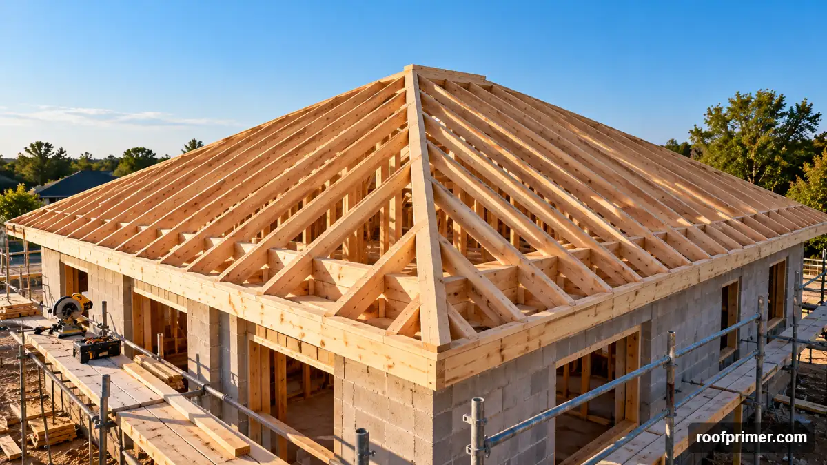
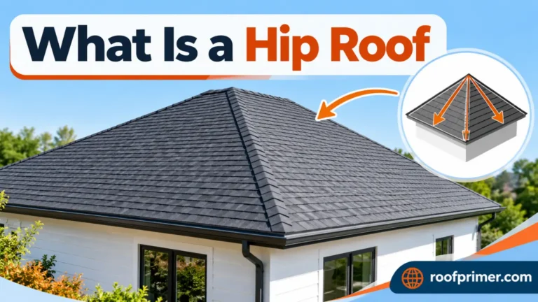
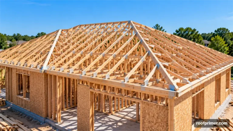
Hip roof framing builds a roof that slopes on all four sides, using a ridge, common rafters, king common rafters, diagonal hip rafters and shorter jack rafters. It takes more layout and cutting than a gable roof, but the finished frame is self-bracing and sheds wind well.
This guide to hip roof framing covers each framing member, how hips and valleys carry load, stick framing vs trusses, the framing layout, a step-by-step build sequence, wind connections, and the mistakes to avoid. It draws on the U.S. Navy’s Builder training manual, the International Residential Code (IRC), the American Wood Council (AWC), PNNL, IBHS and OSHA, plus professional framing references.
Hip Roof Framing Diagram and Anatomy
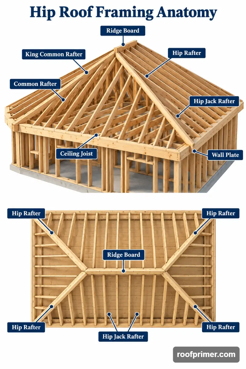
Every hip roof framing plan uses the same core members.
Ridge
The horizontal member at the peak. On most hip roofs it’s a ridge board that the rafters bear against. On low-slope or large roofs, it may need to be a structural ridge beam.
Hips and Hip Rafters
The Navy’s Builder manual describes hip rafters as extending “diagonally from the outside corner formed by perpendicular plates to the ridgeboard.” On an equal-pitch roof they run at 45° in plan view.
Common Rafters
These run at right angles from the wall plate to the ridge, at the main roof pitch.
King Common Rafters
These are the common rafters that meet the ends of the ridge, from the sides and from the center of each hip end. The Navy manual calls them ridge-end common rafters. They lock the ridge in place and set the layout for the hips.
Jacks and Hip Jacks
The Navy manual defines a hip jack as a rafter whose lower end rests on the plate and whose upper end rests against the hip rafter. Each jack is shorter than the next by the same amount, called the common difference.
Valleys and Valley Rafters
On L- and T-shaped roofs, valleys form the inside corners. Vertex Engineering cites the Wood Frame Construction Manual (WFCM) definitions: a hip beam supports jack rafters at an outside corner, forming a convex roof line, while a valley beam supports them at an inside corner, forming a concave one.
Ceiling Joists and Rafter Ties
Rafters push outward at the walls. Ceiling joists or rafter ties tie the walls together and resist that thrust. The IRC requires the ridge to be supported by a wall or girder where neither is provided.
Eaves and Overhangs
On a hip roof, the eaves wrap the whole house, and every rafter tail extends past the wall to form the overhang.
How Hips and Valleys Carry the Load
Understanding the load path is the most important part of hip roof framing.
How a Hip Works Above 3:12
Vertex Engineering explains that on steeper roofs, a hip often acts much like a non-structural ridge board. Opposing jack rafters lean against it and create truss action, as long as ceiling joists or rafter ties resist the outward thrust at the bottom.
When Hips and Ridges Must Be Beams
IRC Section R802.3 requires that where the roof pitch is less than 3:12, members that support rafters, such as ridges, hips and valleys, be designed as beams. The same section requires hip and valley rafters at least 2-inch nominal thickness and no shallower than the cut end of the rafters. They must be braced to a bearing partition or designed to carry their load. On large roofs, the Journal of Light Construction (JLC) describes using glulam or LVL beams for the hips and ridge.
Why Valleys Should Always Be Structural
Vertex notes that a valley “will necessarily behave as a structural beam, no matter the roof slope,” because jack rafters on both sides slope down onto it. In its example, a valley carrying a 10-by-10-foot area needs at least two 2×10s under WFCM Table 3.28. A single member matching the rafter depth can be badly undersized.
The Load Path to the Foundation
Roof loads travel from the sheathing to the rafters, then to the hips, ridge and wall plates, down through the walls and into the foundation. Every connection along that path has to carry both downward loads (roofing and snow) and upward wind uplift.
Stick Framing vs Hip Trusses
Hip roof framing can be built on site or ordered as engineered trusses.
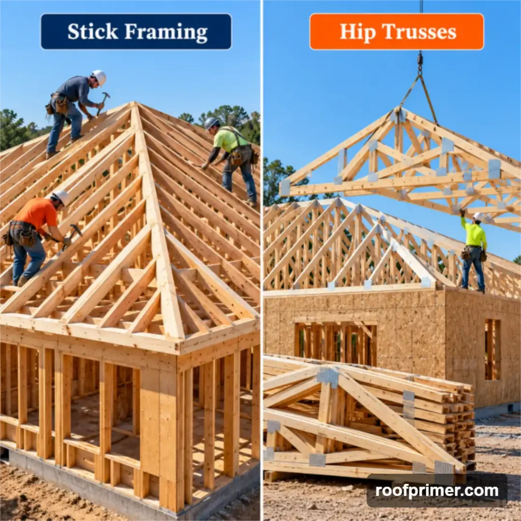
Stick-Framed Hip Roofs
Stick-built hip roof framing means cutting each rafter on site. It allows vaulted ceilings and custom shapes, but it takes skilled layout and more labor.
Engineered Hip Truss Systems
Factory-built hip truss packages use a series of stepped trusses at each hip end. PNNL notes that truss manufacturers use software to analyze wind loads and mark where bracing is required. The IRC requires truss design documents, so follow them exactly.
Engineered Lumber Hips and Ridges
LVL, glulam and PSL members can span farther and carry more load than dimension lumber. They’re common for long hips and structural ridges.
Timber Trusses and Cold-Formed Steel
Custom timber trusses are available with engineer-stamped drawings for exposed or decorative roofs. Hip roofs can also be framed in cold-formed steel. A 2006 American Iron and Steel Institute research report found that unsupported hips carry large compression plus bending, and that a support column at the hip-ridge intersection removes the hip’s axial force. It also found that structural wood sheathing shares load with the rafters and hips.
Planning the Framing Layout
Good hip roof framing starts on paper. JLC advises paying attention to how the roof will be stacked when you calculate lengths and lay out cuts.
The Inputs: Span, Pitch and Ridge Thickness
You need the building span, the pitch and the ridge thickness. JLC recommends subtracting the ridge thickness from the span at the start, so every common, king and hip lands correctly on the ridge.
Laying Out the Wall Plates
The Navy manual places the ridge-end common rafters one-half the span in from each building corner on an equal-pitch hip roof. Mark the commons and jacks on the plates first, then transfer the common rafter layout to the ridge.
Choosing a Jack Rafter Layout
JLC describes two approaches:
- Corner out: jacks are spaced from each corner, so matching jacks are equal, but sheathing gets harder. Truss companies often use this.
- Center out: spacing starts from the center of each hip end, which keeps most of the roof on regular centers and makes sheathing faster.
Sizing Rafters, Hips and Valleys
AWC’s free Span Tables for Joists and Rafters give allowable rafter spans for 2×4 through 2×12 lumber at common load cases. They don’t size hips or valleys. Hips and valleys follow the IRC R802.3 minimums or engineering design, and valleys can be sized with WFCM tables.
How to Frame a Hip Roof Step by Step
This hip roof framing sequence follows the Navy Builder manual and JLC’s method for a regular, equal-pitch hip roof.
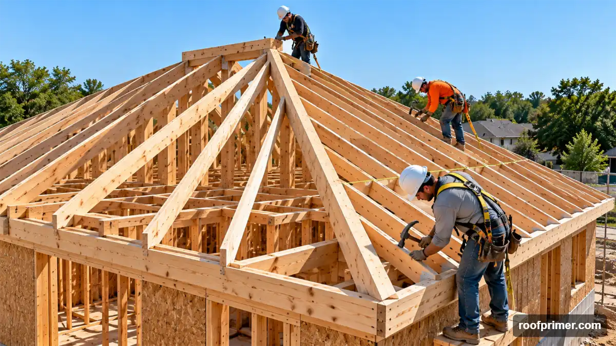
Step 1: Calculate the Common and Hip Rafter Lengths
Hip roof framing math starts with the common run, half the span minus half the ridge thickness.
- Common rafter: common run × √(pitch² + 144) ÷ 12
- Hip rafter: common run × √(pitch² + 288) ÷ 12
The Navy manual notes that “for every 12-inch step in a common rafter, a hip rafter has a 17-inch step,” based on the hip’s 16.97-inch unit run.
In JLC’s 40-by-20-foot example with a double 2×12 ridge (3 inches thick) at 6:12, the common run is 9 feet 10½ inches. That gives commons of about 11 feet ½ inch and hips of 14 feet 9¾ inches. Those figures check out by calculation.
Step 2: Set the Ridge Height
Find the theoretical rise from the run and pitch, then add the height of the rafter above the plate at the seat cut. JLC uses an even 11-inch height above plate to simplify the math.
Step 3: Find the Ridge Length
The theoretical ridge length is the building length minus its width. In practice, JLC measures the adjusted common run in from each end. In the 40-by-20-foot example, 40 feet minus twice 9 feet 10½ inches gives a 20-foot 3-inch ridge, slightly longer than the theoretical 20 feet because of the ridge thickness.
Step 4: Cut the Common and King Common Rafters
Cut the plumb cut at the ridge, the birdsmouth at the plate and the tail cut at the overhang. JLC uses two king commons at each ridge end to hold the hips.
Step 5: Lay Out and Cut the Hips
- Ridge cut: the hip meets the ridge at an angle, so it needs a side cut. The Navy manual calls for a single side cut against the ridge, or a double side cut against the ridge-end commons. JLC uses double cheek cuts.
- Shortening: the Navy manual deducts half the 45° thickness of the ridge, or of the common rafter if the hip frames against the king commons.
- Eaves cut: JLC measures the hip length along its centerline, then sets the seat cut from a line half the hip’s thickness away.
Step 6: Drop or Back the Hips
A hip is usually deeper than the commons, so its top edges can stand above the jacks. The Navy manual gives two fixes:
- Backing: beveling the top edges
- Dropping: deepening the birdsmouth so the hip sits lower
JLC finds dropping faster.
Step 7: Calculate and Cut the Hip Jacks
Each jack gets shorter by the common difference, rafter spacing × pitch factor. The Navy manual’s example gives 19.23 inches at 16-inch spacing on an 8:12 roof. JLC suggests ordering one stick per jack on each hip, cut from stock 2 feet longer than the common.
Step 8: Stack the Roof
JLC’s stacking order:
- Set the ridge, leaving one end long.
- Set the king commons at that end.
- Set the hips at that end.
- At the other end, mark and cut the ridge in place from a king’s plumb cut.
- Set the kings and hips at the second end.
- Fill in the jacks from hip to hip, starting with the shortest, with a string line along each hip to keep it straight.
The Navy manual notes that correctly cut hips will bring the common rafters to plumb.
Step 9: Install Ties, Bracing and Connectors
Install ceiling joists or rafter ties, any required hip or ridge supports, truss bracing per the design documents, and uplift connectors at the wall plates.
Step 10: Sheathe the Roof
Structural sheathing ties the frame together. In high-wind areas, IBHS’s FORTIFIED Roof standard calls for ring-shank nails in an enhanced pattern and a sealed roof deck.
Wind and Uplift Connections
Uplift connections are where hip roof framing meets wind design.
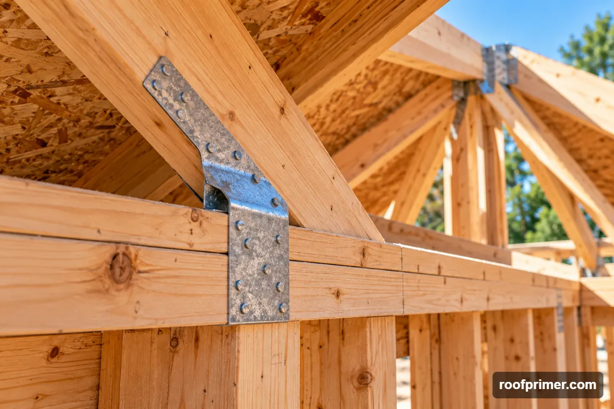
PNNL describes the hip roof as inherently braced against racking, but the frame still has to resist uplift. IRC Section R802.11 sets uplift resistance requirements for rafter- and truss-to-wall connections. A 2023 County of Hawai’i building memo notes that the IRC’s Table R802.11 only covers rafters with overhangs of up to 2 feet, and adds values for longer overhangs.
In hurricane-prone areas, IBHS’s FORTIFIED program goes further, with engineered roof-to-wall, story-to-story and wall-to-foundation connections. Hurricane ties or straps at every rafter or truss keep the load path continuous.
Framing Cross-Hipped and L-Shaped Roofs
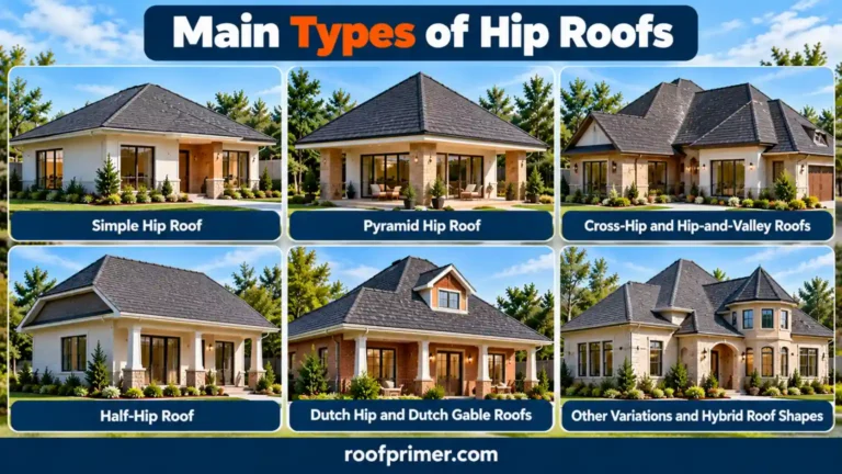
In cross-hipped hip roof framing, each inside corner where two sections meet becomes a valley. Frame the main roof first, then the intersecting wing. Treat each valley as a structural beam, support its upper end properly, and fill in valley jacks running from the valley up to the ridge. Vertex’s case studies show that undersized or unbraced valley members can crack under heavy snow.
Materials Used in Hip Roof Construction
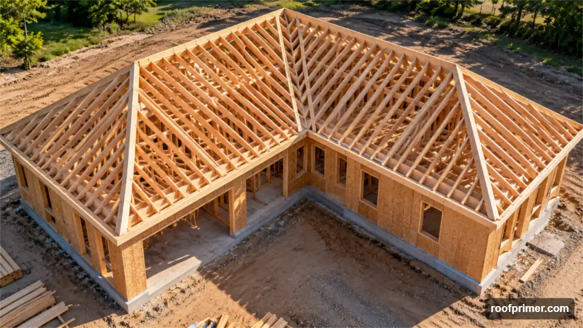
Typical hip roof framing materials include:
- Framing: dimension lumber for rafters and jacks, and LVL, glulam or PSL for long hips and structural ridges
- Connectors: joist and rafter hangers, hurricane ties and straps
- Sheathing: plywood or OSB structural panels
- Roof covering: most often asphalt shingles, plus metal, tile and slate within their IRC minimum slopes
Tools and Safety
Hip roof framing needs accurate layout tools and proper fall protection.
- Layout tools: a framing square with rafter tables, which the Navy manual notes apply only to equal-pitch hip roofs
- Calculators: construction calculators and apps with hip and valley functions, which JLC uses
- Lines and marking: string lines and story poles
- Saws: a circular saw or beam saw for deep hips
OSHA requires fall protection for residential construction work six feet or more above a lower level (29 CFR 1926.501(b)(13)). Accepted methods include guardrail systems, safety net systems and personal fall arrest systems.
Inspection Checkpoints Before Roofing
Check the hip roof framing against this list before any roofing goes on.
- Hips are straight from corner to ridge
- Hips sit flush with the jacks, whether dropped or backed
- Rafters are plumb, with full bearing at the plates
- Ceiling joists or rafter ties are installed and connected
- Valleys are sized and supported as beams
- Uplift connectors are installed at every rafter or truss
- Truss bracing matches the design documents
- The sheathing nailing pattern is correct
Common Hip Roof Construction Mistakes
These are the hip roof framing errors that show up most often.
- Using the common rafter length × √2 for the hip: apply √2 to the run, not the sloped length.
- Forgetting to subtract the ridge thickness: the hips and commons won’t meet the ridge correctly.
- Undersized valley members: valleys are structural beams at any slope.
- Unbraced hips on low-slope roofs: below 3:12, hips must be designed as beams.
- Missing rafter ties: without them, a hip loses its truss action.
- Skipping uplift connectors: these are critical in high-wind areas.
- Using framing square tables on unequal-pitch roofs: the tables only work when every pitch is equal.
When to Hire a Framer or Engineer
Hip roof framing on a simple rectangle is a skilled carpentry job. Bring in an engineer for:
- Low-slope roofs
- Long spans
- Valleys and structural ridges
- Vaulted ceilings without ceiling joists
- Heavy roofing materials
- High-wind or heavy-snow areas
Most jurisdictions require a permit for new roof framing. Truss systems come with their own engineered design documents.
Conclusion
Successful hip roof framing comes down to accurate layout, correct hip lengths and cuts, a straight stacking sequence, and a complete load path from sheathing to foundation. Know which members carry load, especially valleys and low-slope hips, and tie the walls together with ceiling joists or rafter ties. Then finish with uplift connectors and properly nailed sheathing, and have complex or low-slope roofs reviewed by an engineer.
Frequently Asked Questions
Are hip rafters always 45 degrees?
Only in plan view, and only when both roof planes share the same pitch. With unequal pitches, JLC explains, the hip doesn’t sit at 45° and lands on the wall plate supporting the steeper roof. The hip’s slope is also shallower than the commons, such as 19.5° at 6:12.
What is the correct angle for a hip roof?
There’s no single correct angle. The pitch must meet the roofing material’s minimum slope and suit local wind and snow design. Below 3:12, the IRC requires hips and valleys designed as beams.
What are the downsides of a hip roof?
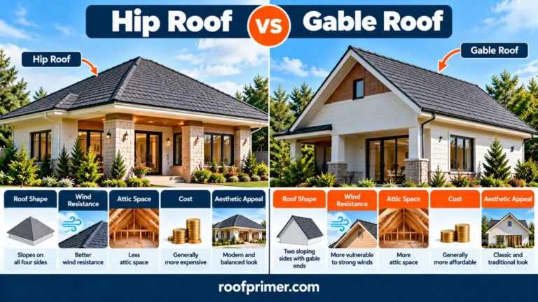
The main downsides are more complex framing and cuts, higher labor and material cost, less attic space, more hips and valleys to flash, and engineered members on low pitches.
What is the formula for a hip roof?
Hip run = common run × 1.414, about 17 inches per 12 inches of run. Hip rafter length = common run × √(pitch² + 288) ÷ 12. The theoretical ridge length is the building length minus its width. Then shorten the hip by half the 45° thickness of the ridge.
How do you calculate the pitch of a hip roof?
Pitch = rise ÷ run × 12, so a roof rising 7 feet over a 14-foot run is 6:12. The hips run at a shallower pitch, the common pitch divided by √2.
Does a hip roof need a ridge beam?
Not usually. Above 3:12, with ceiling joists or rafter ties in place, a ridge board works. Below 3:12, or without ties, the IRC requires a ridge designed as a beam or supported by a wall or girder.
Can you frame a hip roof without ceiling joists?
Yes, for vaulted ceilings, but the outward thrust must be handled another way, usually with a structural ridge beam and engineered hips. Have an engineer design it.
What size lumber is used for a hip rafter?
The IRC requires a hip rafter at least 2-inch nominal thickness and no shallower than the cut end of the rafters. Long hips often use LVL or other engineered lumber, and low-slope hips must be designed as beams.
Can a homeowner frame a hip roof?
An experienced DIYer can frame a small, simple hip roof, but hip roof framing layout and compound cuts are demanding. Most homeowners hire a framer, especially for full houses, complex roofs or high-wind areas, and a permit is usually required.